
Written and reviewed by the SG Power technical team at SG Power Products Pvt. Ltd. | Last updated: 4 November 2026
This exothermic welding procedure walks a site team through one complete joint, from checking materials to recording the finished weld. It is written as a practical exothermic welding method statement for site engineers, supervisors, welders and quality inspectors on earthing and lightning protection projects.
The exothermic welding process, sometimes called cad welding or thermite welding, makes permanent exothermic connections. It is used on substation earth grids, solar plants, telecom towers, steel structures and buildings, and in lightning protection systems. Follow this guide on how to make an exothermic weld with the graphite mould, powder and conductor sizes shown on your earthing drawing. For mould types, joint codes and mould care, see SG Power's exothermic mould page.
In short, the exothermic welding procedure has eight stages. Plan the joint, gather tools and PPE, and prepare the site and conductors. Then set up the mould, load and ignite the charge, open and clean, and inspect and record. Each joint takes a few minutes, most of it preparation and cooling.
| Stage | What Happens | Key Check |
|---|---|---|
| 1. Plan | Match each joint to its mould and cartridge | Mould label matches joint type and conductor sizes |
| 2. Tools and PPE | Gather the kit and protective gear | Hot work permit issued where required |
| 3. Site | Make the work area dry, clear and safe | No water, debris or flammables near the joint |
| 4. Conductors | Clean, dry and position the conductors | Bright metal, correct size, no gaps |
| 5. Mould | Dry, assemble and clamp the mould | Mould closed tightly and level |
| 6. Weld | Load disc, powder and starting powder; ignite | Everyone at a safe distance |
| 7. Open and clean | Wait, open, remove slag, clean the mould | Joint set before the mould is moved |
| 8. Inspect and record | Check the joint and log it | Full fill, no large pores, record completed |
Based on standard exothermic welding practice and the earthing standards listed under Sources. Reviewed November 2026.
SG Power makes graphite exothermic moulds, weld powder cartridges and welding accessories in its own factory in India, so everything in this procedure comes from one source. Share your earthing drawing or joint list, and the team will match a mould and cartridge to every joint.
| What SG Power Provides | How It Helps This Procedure |
|---|---|
| Graphite moulds for each joint type and conductor size | The right mould for every joint on your list |
| Weld powder cartridges with steel discs and starting powder | Cartridge weights matched to each mould label |
| Handle clamps, flint igniters and cleaning tools | A complete kit for the welding crew |
| Joint list and quantity support | Moulds, cartridges and spares worked out from your drawing |
| Help with first joints | Guidance for new crews on trial welds |
An exothermic welding method statement is a written procedure that explains how joints will be made safely and to a consistent standard on a project. It lists the scope, standards, responsibilities, tools, PPE, step-by-step method, inspection checks and records. Consultants and main contractors often ask for one before welding starts.
| Section of the Method Statement | What It Covers |
|---|---|
| Scope | Which joints, systems and areas the procedure covers |
| References | Earthing drawing, specification, IEEE 80, IEEE 837, IS 3043 (earthing) and IS 3016 (fire safety in welding) |
| Responsibilities | Site engineer, supervisor, welders, quality inspector and safety officer |
| Materials and tools | Moulds, powder cartridges, clamps, igniters, cleaning tools |
| Health and safety | PPE, hot work permit, fire precautions and safety data sheet |
| Procedure | The step-by-step method in this guide |
| Inspection and testing | Quality control (QA/QC) checks, an inspection and test plan (ITP), visual checks and resistance or continuity tests |
| Records | Weld log, photos and test results |
| Role | Responsibility in the Procedure |
|---|---|
| Site engineer | Approves the method statement, joint list and mould selection |
| Supervisor | Checks set-up before each weld, signs the weld log and stops work in unsafe conditions |
| Welder | Prepares, sets up and makes each joint as per this procedure |
| Helper | Cleans conductors and moulds, hands over tools and keeps the area clear |
| Quality inspector | Inspects joints, records results and approves backfilling |
| Safety officer | Issues the hot work permit and checks PPE and fire precautions |
Plan each exothermic joint by reading the earthing drawing and listing every joint by type, conductor sizes and position. Match each joint to a graphite mould made for it and the cartridge weight printed on that mould's label. Check that enough moulds, cartridges and spares are on site before starting.
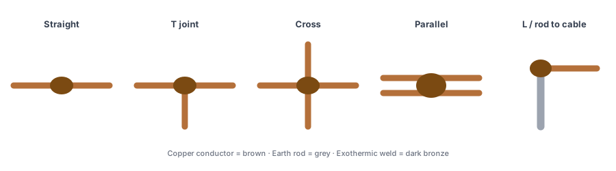
List every joint: straight, tee, cross, cable to rod, strip to strip, cable to strip or surface to steel
Note conductor sizes, such as 70 sq mm copper cable, 25×3 mm copper strip or a 17.2 mm copper bonded earth electrode
Note the joint position: horizontal, vertical or on a surface
Match each joint to its mould and read the cartridge weight on the mould label
Allow spare cartridges for damp, damaged or failed welds
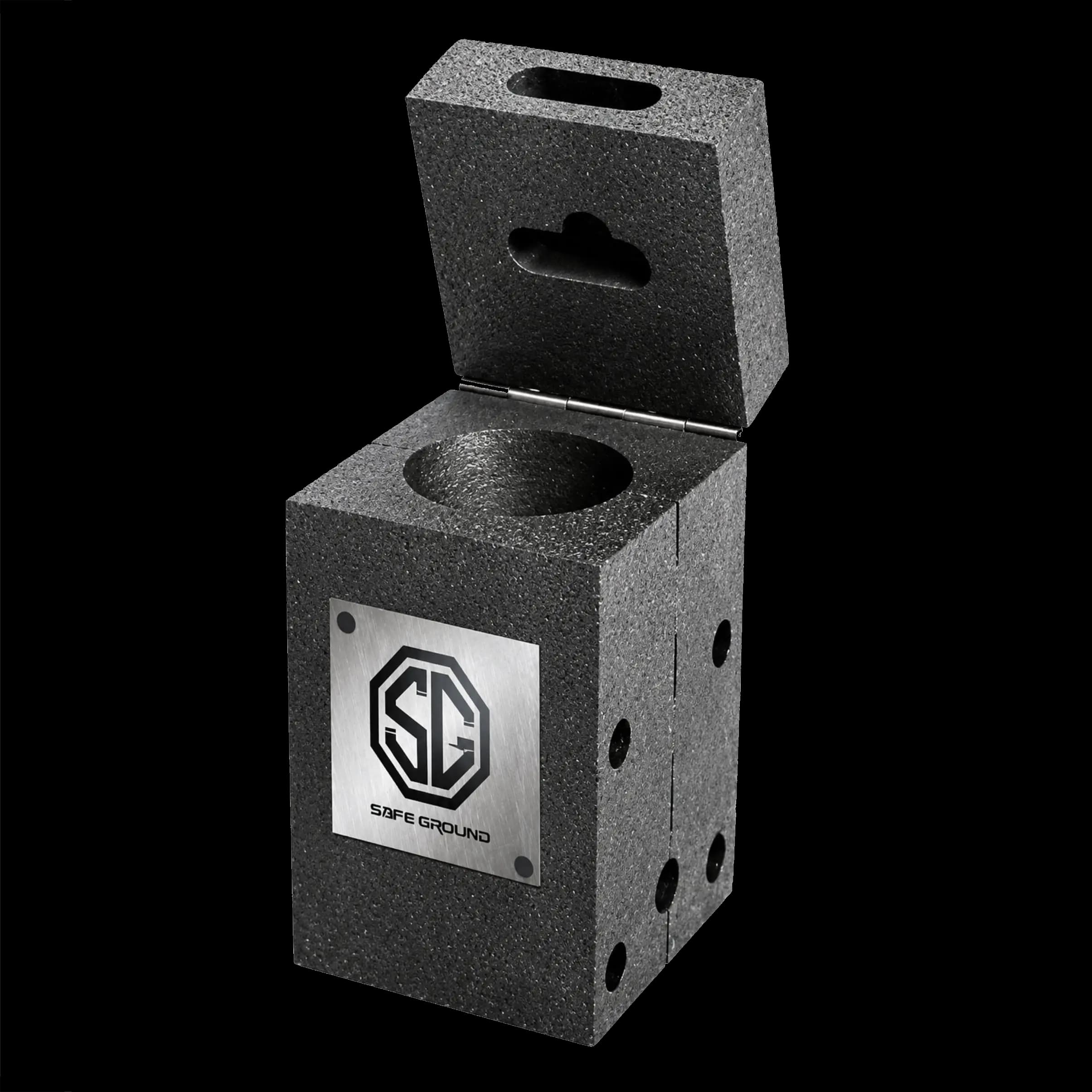
For joint shapes and mould codes such as CC, CR and CB, see the exothermic mould types on the mould page.
Exothermic welding needs a graphite mould, a handle clamp, powder cartridges with steel discs and starting powder, a flint igniter, and cleaning tools. The welder needs heat-resistant gloves, safety glasses and full-sleeve cotton clothing. A gas torch or heater dries the mould before the first weld.
| Tool or Item | Purpose |
|---|---|
| Graphite mould | Holds the conductors and shapes the joint |
| Handle clamp | Locks the mould halves shut |
| Powder cartridges, steel discs, starting powder | Make the molten copper for each weld |
| Flint igniter | Lights the starting powder from a safe distance |
| Wire brush, file or grinder | Cleans conductors to bright metal |
| Mould cleaning brush and scraper | Removes slag from the mould after each weld |
| Mould sealer (putty) | Closes small gaps around conductors |
| Gas torch or heater | Dries the mould and conductors |
| Cable cutter | Cuts conductors square and clean |
| Fire extinguisher | Ready at the work area |
| PPE | Why It Is Needed |
|---|---|
| Heat-resistant gloves | Protect hands from the hot mould and slag |
| Safety glasses or face shield | Protect eyes from sparks and flashes |
| Full-sleeve cotton clothing | Synthetic fabrics can melt onto skin |
| Safety shoes | Protect feet from hot slag and heavy tools |
Matching moulds to your joint list? See SG Power's exothermic mould types and the exothermic welding tools and accessories used in this procedure.
Prepare the work area for exothermic welding by making it dry, clear and safe before any mould is opened. Pump out trench water, cover the area from rain, and remove leaves, paper, fuel and other flammables. Get a hot work permit where the site requires one, and keep a fire extinguisher close by.
Pump out water and let wet ground drain before welding in a trench
Cover the work area from rain and strong wind
Clear leaves, packaging, fuel and other flammables from around the joint
Keep people who are not involved at a safe distance
Keep dry sand ready to control any small fire; never use water near molten copper
When welding indoors or in a pit, keep air moving so smoke does not build up
Never weld near flammable gas or vapour without a gas test and permit
Follow the fire precautions for welding in IS 3016, the Indian code for fire safety in welding and cutting
| Site Condition | Effect on the Weld | What to Do |
|---|---|---|
| Monsoon rain or high humidity | Moisture in moulds and conductors; porous welds | Cover the area, dry the mould before each weld and stop in rain |
| Strong summer sun | Moulds left in the sun can overheat between welds | Keep moulds shaded and allow a few minutes between welds |
| Wind | Blows away starting powder and carries smoke to the welder | Shield the mould and stand upwind |
| Dust | Dirt in the mould cavity and on conductors | Clean conductors and the mould just before each weld |
Prepare conductors for exothermic welding by cutting them square, cleaning them to bright metal and drying them completely. Remove oil, paint, mud, oxide and loose zinc from the joint area. Check each conductor fits the mould openings snugly, because gaps let molten copper leak out.
| Conductor | How to Prepare It |
|---|---|
| Copper cable | Cut square, clean strands with a wire brush, keep strands together |
| Copper or copper bonded strip | Brush to bright metal and dry |
| Copper bonded earth rod | Clean the rod top or side where the joint will sit |
| GI strip (galvanised) | Remove loose zinc and dirt at the joint area |
| Steel surface, pipe or rebar | Grind or file to bright steel; remove rust and paint |
Dry damp conductors gently with a torch before setting the mould. Wet conductors are a leading cause of porous welds.
Set up the graphite mould for an exothermic weld by drying it, placing the conductors in their openings and closing it tightly with the handle clamp. Check that the mould sits level and the conductors are fully inside the weld cavity. Seal any small gaps with mould sealer, so molten copper cannot escape.
Dry the mould: warm it with a gas torch or heater before the first weld of the day, or whenever it has cooled and picked up moisture. Some mould instructions give a preheat of about 120°C; follow your mould’s sheet.
Fit the clamp: attach the handle clamp and check it closes the mould halves fully.
Position the conductors: place them in the openings so they meet in the middle of the weld cavity.
Close and lock: close the mould and lock the clamp firmly.
Level and support: keep the mould level and support it so it cannot move.
Seal gaps: press mould sealer around any gap at the conductor openings. For a small cable in a larger opening, use the copper adapter sleeve the mould instructions specify.
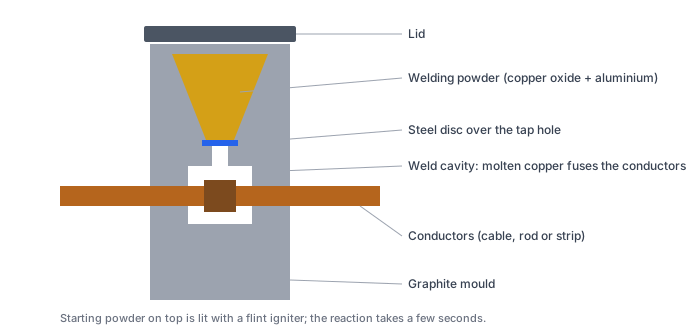
Load the exothermic charge by placing the steel disc in the crucible over the tap hole, pouring in the weld powder, then adding the starting powder as the pack instructs. Close the lid, stand to one side and ignite the starting powder with a flint igniter. The reaction lasts a few seconds.
Disc first: place the steel disc in the crucible so it covers the tap hole.
Pour the powder: empty the cartridge of the weight on the mould label into the crucible, without stirring it.
Add starting powder: tap the pack so all of it comes out, and spread it as instructed.
Close the lid: shut the mould lid over the crucible.
Clear the area: everyone stands back and to one side of the mould.
Ignite: point the flint igniter at the lid opening and strike it.
Never use a match or lighter, never look into the crucible or at the flash during the reaction, and never add a second cartridge to the same weld. Electronic igniters, where used, let the welder start the reaction from further away.
Open the exothermic mould only after the copper has set, usually a short wait after the reaction ends. Release the clamp, open the mould carefully and lift it off the joint. Brush away the slag from the joint, then clean the crucible, tap hole and cavity before the next weld.
Wait until the metal has set before moving the clamp
Open the mould gently to avoid chipping the graphite
Knock off and brush away slag from the joint once cool enough to handle
Clean the crucible, tap hole and weld cavity with the brush and scraper
Check the mould for cracks or worn openings before the next weld
Keep the mould warm and dry between welds
Wait a few minutes between exothermic welds, so the mould is warm and dry but not hot enough to set off the next charge early. Mould instructions commonly advise around five minutes and warn against loading powder into a very hot mould. On fast-moving work, use two moulds in turn.
Inspect each exothermic weld once it cools: the joint should be smooth, solid and fully filled, with the conductors fused into the copper. Cut out and re-weld any joint with large pores, incomplete fill or exposed conductors. Record every joint in a weld log with its location, mould, batch and result.
| Inspection Check | Accept | Re-Weld |
|---|---|---|
| Fill | Joint fully formed around the conductors | Conductors visible or joint incomplete |
| Surface | Smooth, with only small surface pinholes | Large pores or a sponge-like surface |
| Fusion | Conductors fused into the copper | Conductors loose or not bonded |
| Slag | Removed, with no slag inside the joint | Slag trapped in the joint |
| Shape | Matches the mould shape | Large overflow or missing sections |
| Sound check | A firm, solid joint when tapped with a small hammer | Cracks, loose parts or a hollow sound |
| Weld Log Field (Template) | Example |
|---|---|
| Joint number and location | J-045, earth pit 7 |
| Joint type and conductors | Cable to rod, 70 sq mm cable to 17.2 mm rod |
| Mould and cartridge | Cable-to-rod mould, cartridge weight per mould label |
| Powder batch number | From the cartridge pack |
| Welder and date | Name, date and time |
| Result | Accepted, or re-welded and accepted |
| Photo | Before and after cleaning |
A good joint has a cross-section larger than the conductors, so it carries at least as much current as they do. Inspect buried joints before the trench is backfilled, and coat pipe and structure welds with the protective compound the specification requires. Some specifications also ask for resistance (micro-ohm) or continuity tests across selected joints. A complete weld log gives full traceability from each joint back to its powder batch. Where a joint must stay open for testing, use bolted earthing clamps at the test point instead of a weld.
Planning an earthing project? See SG Power's exothermic mould and exothermic weld powder pages for joint types, cartridge sizes and accessories.
An exothermic welding risk assessment, or job safety analysis (JSA), lists each hazard, its risk and the control that keeps workers safe. The main hazards are molten metal, hot moulds, sparks and fire, smoke, bright flash, moisture, and manual handling in trenches. Most method statements include a table like this one.
| Hazard | Risk | Control |
|---|---|---|
| Molten metal spray | Burns | Dry moulds and conductors; stand to one side during ignition |
| Hot mould, clamp and slag | Burns | Wait for cooling; use gloves and the clamp handle |
| Sparks and spilled metal | Fire | Clear flammables; keep dry sand and an extinguisher ready; heat-resistant sheet under the mould |
| Bright flash | Eye strain | Safety glasses; do not look at the reaction |
| Smoke | Inhalation | Ventilate pits and indoor areas; stand upwind |
| Water near the reaction | Steam eruption | Pump out trenches; stop work in rain |
| Trenches and pits | Falls and collapse | Shore or slope trenches as the site rules require; use safe access |
| Unauthorised people | Injury | Barricade the work area during welding |
Go through this table with the crew in a toolbox talk before work starts each day.
An exothermic welding procedure diagram shows a graphite mould in cross-section. The crucible at the top holds the powder, the steel disc sits over the tap hole, and the conductors meet in the weld cavity below. Arrows show the molten copper running down from the crucible into the cavity.
| Part in the Diagram | Role in the Procedure |
|---|---|
| Lid with opening | Closes the crucible; the flint igniter sparks through the opening |
| Crucible | Holds the weld powder and starting powder during the reaction |
| Steel disc | Holds the powder until the copper is fully molten, then melts |
| Tap hole | Channels the molten copper from the crucible down to the joint |
| Weld cavity | Shapes the joint around the conductors |
| Conductor openings | Hold the conductors in position and keep molten copper in |
| Handle clamp | Keeps the mould halves locked shut |
The diagram at the top of this guide shows these parts. For mould types and codes, see the exothermic mould page.
Common exothermic weld defects are porosity, incomplete fill, metal leaking from the mould, slag inclusions and a sticking or cracked mould. Most come from moisture, dirty conductors, a loose clamp, the wrong cartridge or a worn mould. Fix the cause, cut out the bad joint and weld it again.
| Defect | Likely Cause | Fix |
|---|---|---|
| Porosity (pinholes or sponge-like surface) | Moisture in the powder, mould or conductors | Dry the mould and conductors; use a fresh, sealed cartridge |
| Incomplete fill | Cartridge too small, metal leaking or conductors misplaced | Use the weight on the mould label; check the clamp and conductor position |
| Metal leaking at the openings | Gaps around conductors or worn openings | Use mould sealer; replace a worn mould |
| Slag in the joint | Dirty conductors or uncleaned mould | Clean conductors and the mould cavity before each weld |
| Powder fails to ignite | Damp or old powder, or starting powder left in the pack | Use fresh, dry powder and tap out all the starting powder |
| Molten metal spitting out | Water in the mould, conductors or trench | Stop, dry everything and protect the area from water |
| Mould cracks or chips | Rough handling, over-tightening or moisture | Handle and clamp gently; dry before use; replace cracked moulds |
Exothermic welds fail on site mostly because of moisture, a mould that is not level, or binding conductors, say electricians on trade forums such as Mike Holt. They also stress practising dry runs and never improvising missing parts. Indian forums have little discussion of the procedure itself.
| Site Lesson | What to Do |
|---|---|
| Trench dewatered, but welds still spill | The cable is probably still wet; dry it thoroughly before every weld |
| Molten metal spills from the top of the mould | Check the mould is level and the conductors are not binding in the openings |
| New crew making its first joints | Practise dry runs and trial welds in good conditions before project work |
| Tempted to improvise a missing steel disc | Never improvise; use the disc packed with each cartridge |
Use this exothermic welding procedure checklist before and after every joint. It condenses the eight steps into quick checks a supervisor can print and tick on site. A joint that fails any check before welding should not be welded until the problem is fixed.
Correct mould for the joint type and conductor sizes
Cartridge weight matches the mould label
Hot work permit issued, if required
Work area dry, clear of flammables and protected from rain
Conductors cut square, clean, bright and dry
Mould dry, clamped tightly, level and sealed
Steel disc in place, powder poured, starting powder added
PPE worn and people clear of the mould
Metal set before the mould was opened
Slag removed and the mould cleaned
Joint smooth, solid and fully filled
Joint recorded in the weld log, with a photo
Training a new welding crew? Share your joint list with SG Power's technical team through the contact page for help with moulds, cartridges and first-joint support.
These are the main facts about the exothermic welding procedure, written as short statements for quick reference:
Stages: plan, tools and PPE, site, conductors, mould, weld, open and clean, inspect and record.
Biggest risk: moisture in the powder, mould, conductors or trench.
Right charge: the cartridge weight printed on the mould label.
Mould set-up: dry, tightly clamped, level and sealed.
Ignition: a flint igniter, with everyone standing to one side.
Inspection: smooth, solid and fully filled joints; re-weld any that fail.
Records: a weld log with joint, mould, batch, welder, date, result and photo.
This procedure follows standard exothermic welding practice and the earthing standards that project specifications usually name. Always follow the moulds' labels, the powder's safety data sheet, your project specification and the site's safety rules, because joint and site requirements vary.
IEEE 80, Guide for Safety in AC Substation Grounding
IEEE 837, Standard for Qualifying Permanent Connections Used in Substation Grounding
IS 3016, Code of Practice for Fire Precautions in Welding and Cutting Operations
OSHA 1910.252, US rules for fire prevention and protection in welding, cutting and brazing
IS 3043, Code of Practice for Earthing, published by the Bureau of Indian Standards
Mike Holt electrical forum threads on exothermic welding problems and technique (checked November 2026)
Exothermic welding instruction sheets and method statements from mould makers, and a municipal standard detail for exothermic cable-to-pipe welds (checked November 2026)
To go further, these pages cover the moulds, powder and accessories used in this procedure, and explain the process and materials in more depth. They help when you are choosing moulds for a new project or training a new crew.
Earth pits on a completed system are closed with an earth pit cover once every joint has been inspected and recorded.